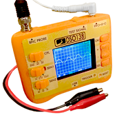
I was browsing DX as usual when something interesting caught my eye: a DIY oscilloscope kit. Previously I considered buying a $140 digital oscilloscope, but decided to pass when I saw the device had poor reviews. I still wanted one, even if it was crappy – just not for $140. When I saw this kit for only $30, I got excited at the opportunity to 3D print a custom case.
The board already had the difficult surface-mount components pre-attached for me – so all I would need to do is solder a million through-hole components.
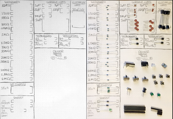
I sorted all my components by value and made a little chart for easy access:
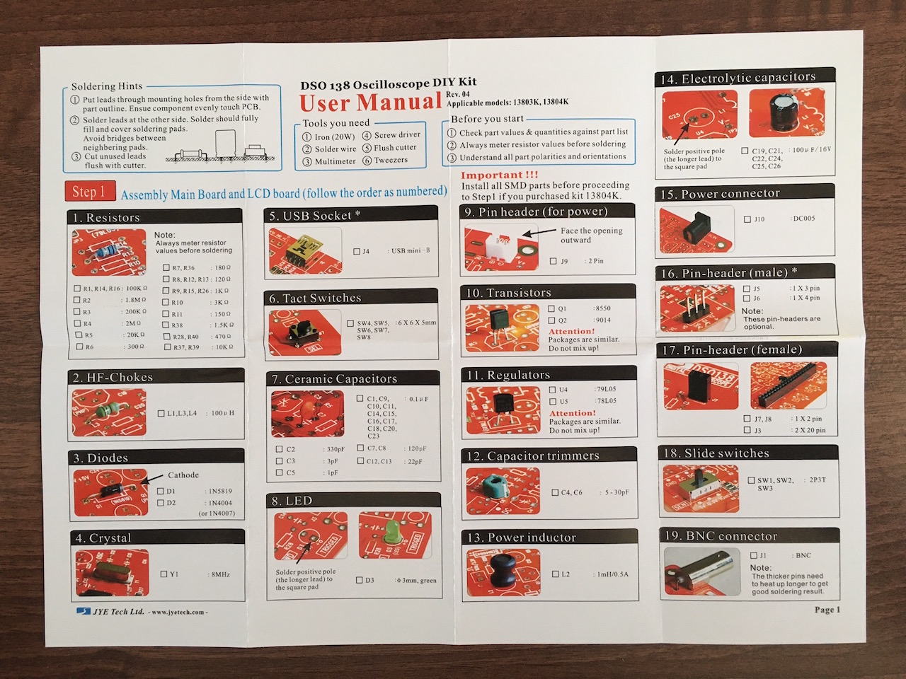
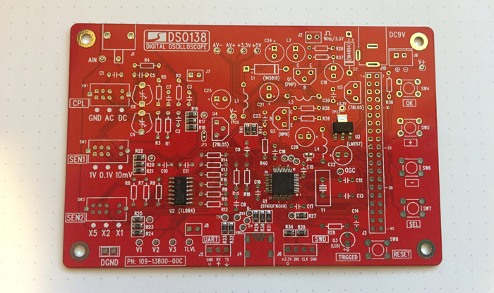
After I was all set up, I got to work. The instructions were clear enough – just match the part number to it’s holes and solder down. The instructions go from order of lowest components to tallest, which makes sense for soldering. (Instructions imaged borrowed from igorkromin.net)
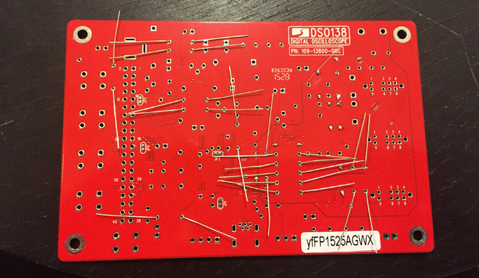
I attached them in batch groups by bending the pins to keep them in place, and then soldering several at once:
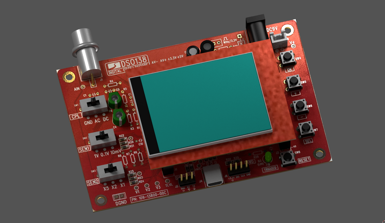
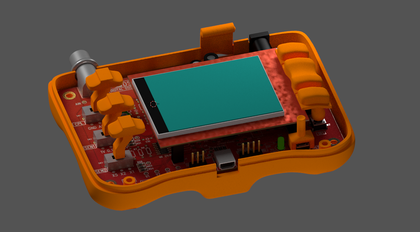
To make a long story short, I finished the device and got it working. Now it was time to make a case! I started by making a hyper-realistic model of the board. I ran to Harbor Freight and picked up a cheap caliper since I must have left mine back in Calfornia. After hours of anally measuring the real product, I had my model:
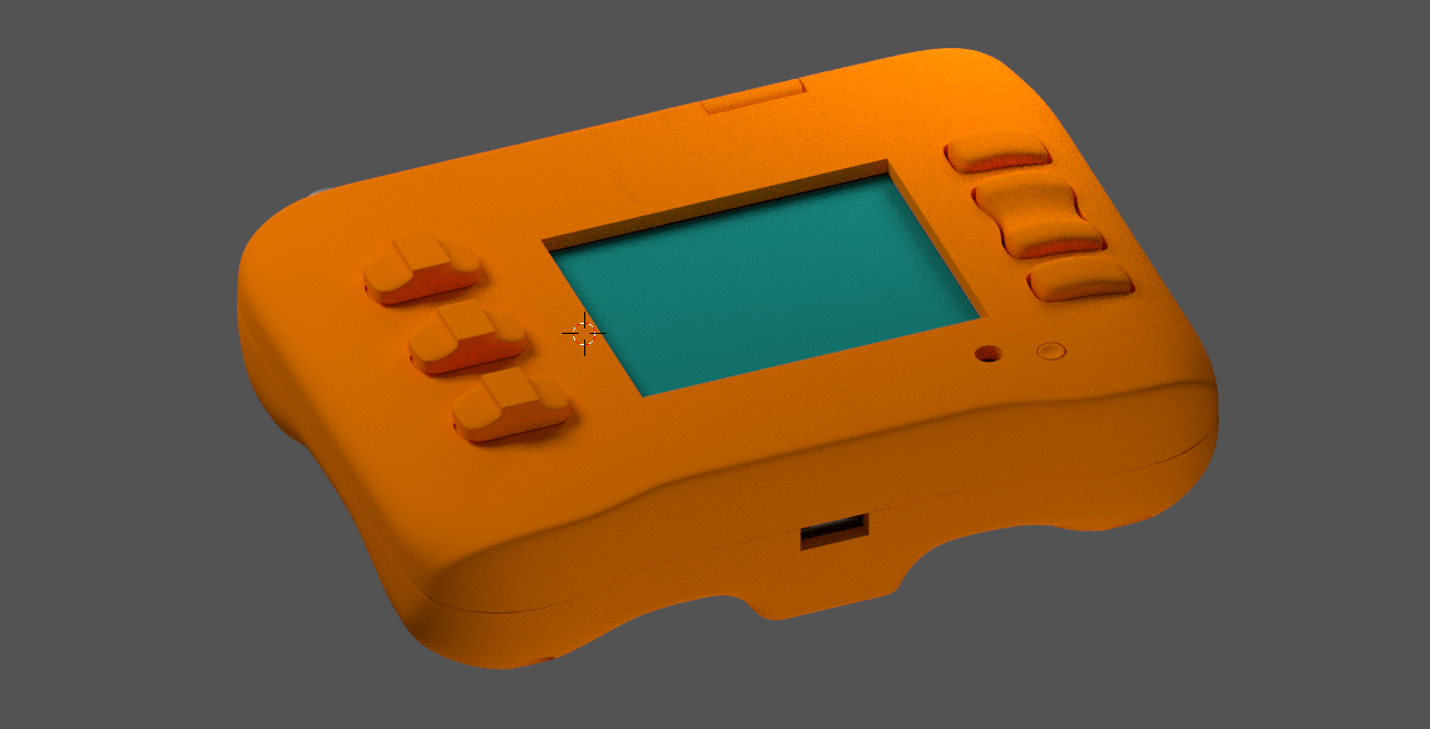
Then I modeled a sweet looking case around it:
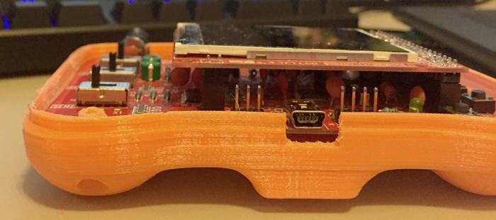
I made sure to cut holes for the power, coaxial connector, usb and test lead:
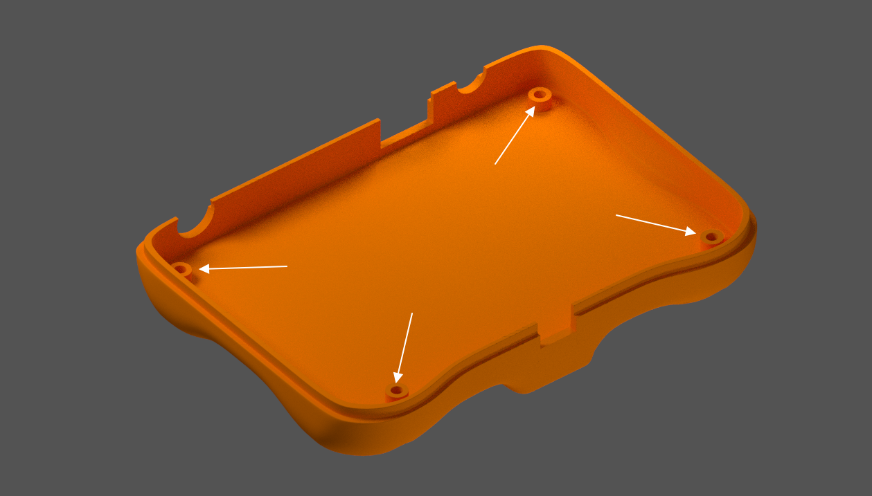
And I added pegs for screws to mount the board to the plastic, as well as screw the case halves together:
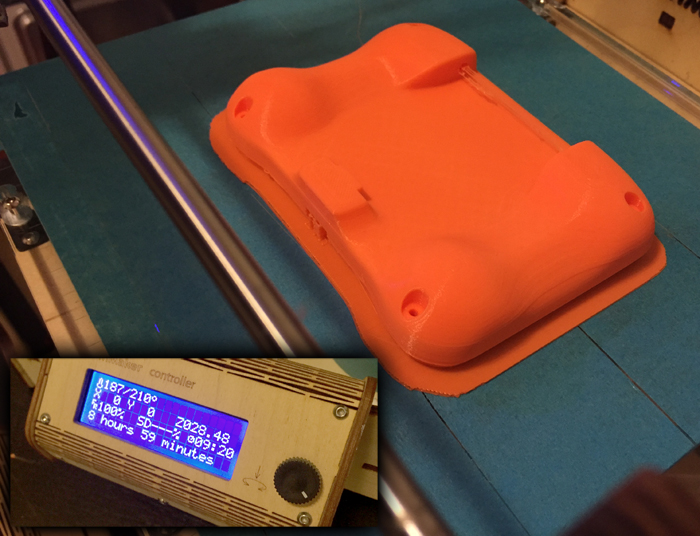
After a balancing act of space issues, I got everything the way I wanted it and sent the first half to the printer… 9 excruciating hours later, the bottom was done!
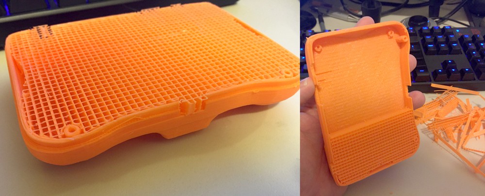
Because I wanted the surface finish to look good, I printed it upside down so all the support material would be on the inside. This is probably why it took so long – it had to build support for the entire interior. It felt really good to rip it all out, though:
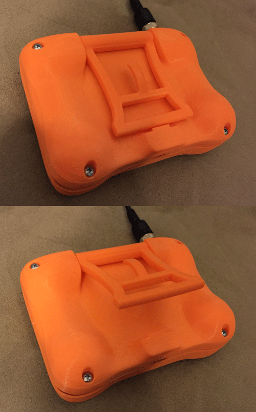
I also had designed a fold-out stand for the device, which I printed next, to make sure it fit in the back. It’s a about 2mm shorter than I’d like – so it doesn’t quite snap shut. One day I’ll print another. Otherwise, it worked well:
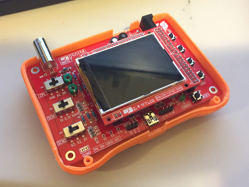
Yay things fit, my measurements were mostly correct!
And from the front:
I had some printer issues, so I had to print the top multiple times but eventually it came out. I also printed the buttons and the slider tabs.
Now, the mount-pegs for the screws weren’t threaded. I didn’t want to crack the plastic by forcing a screw into the holes, so I came up with a useful solution for making threading screw holes. I got a nail that was approximately the same diameter and heated it red hot on my stove’s open flame. I then used vice-grips to slowly dip the hot nail down the screw channels, melting the plastic as it went. I quickly removed the nail, and while still melted, I drove a screw into the channel. I let it cool off with the screw in place. The effect was the plastic hardening with the perfect spiral shape for the screws I was using. I did this 10 times total and when I was all done everything screwed together perfectly without stressing the plastic.
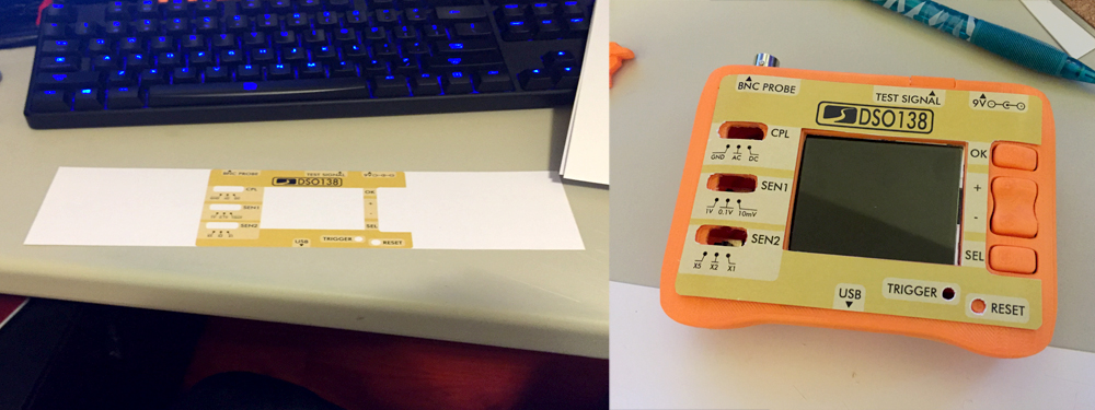
Next I designed a graphic to label the buttons and ports on top. I ran to FedEx Kinkos and had them print out a high quality 300 DPI print on glossy paper. I cut it out with a razor and it fit perfectly:
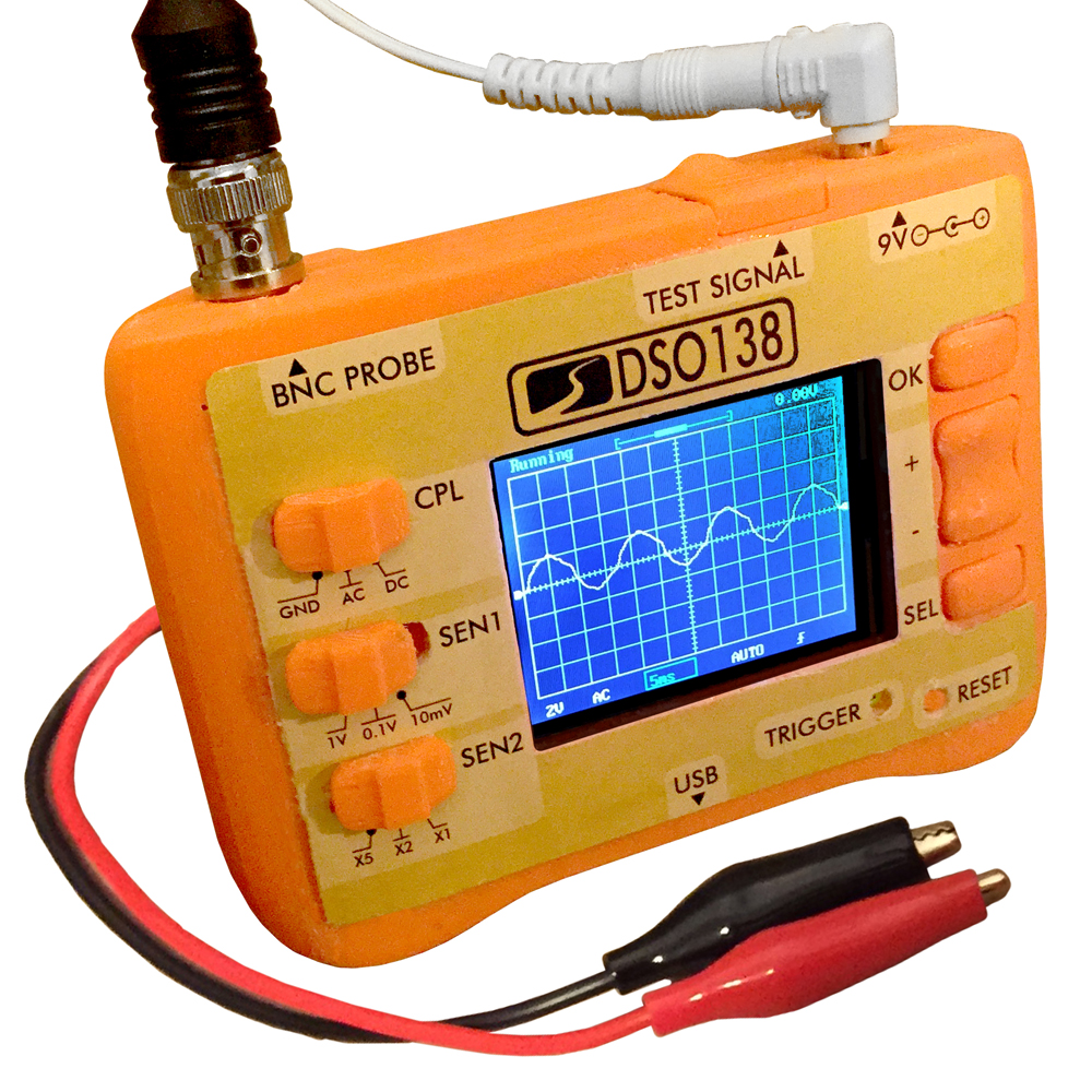
Unfortunately I put too much glue and it leaked out around the edges. This really detracted from the final quality and I’m slightly disappointed in myself. I was able to clean it up a bit, though. So here’s my one-of-a-kind DSO138:
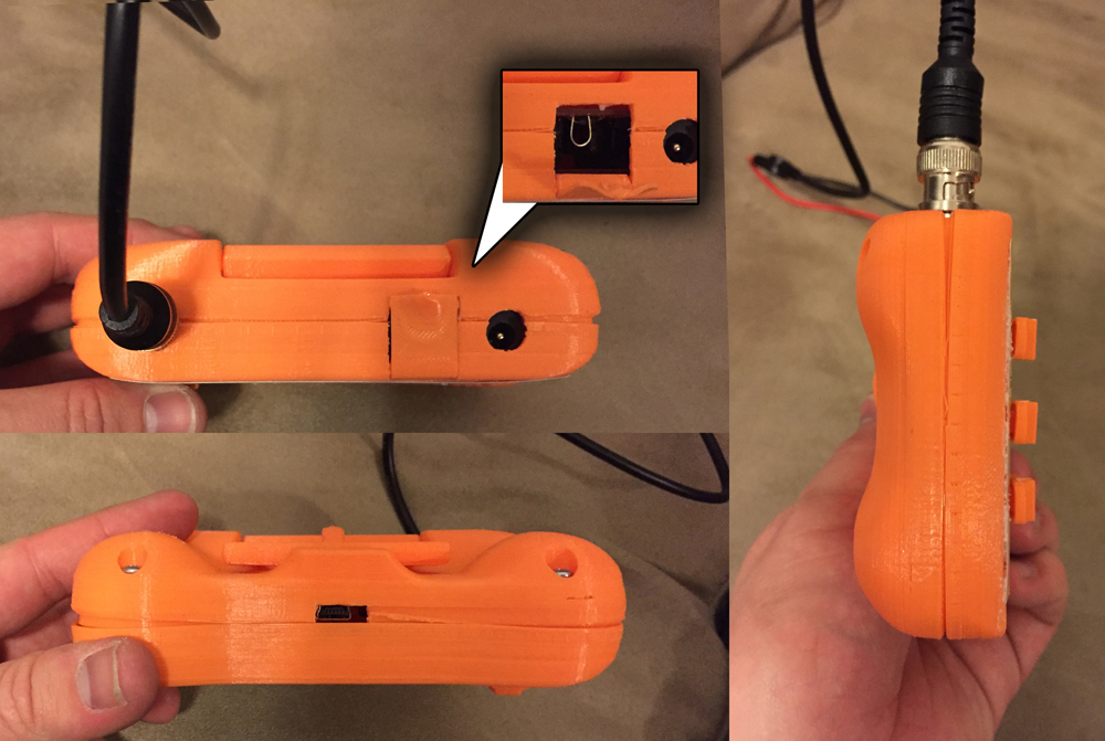
Here’s side side views of the ergonomic grips and the “test lead” door on the top.
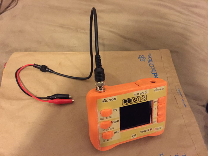
All done!
February 28, 2016 at 4:07 am | Other Projects
